

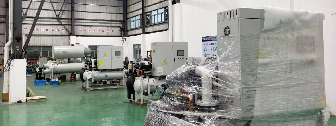
The system cools calcium hydroxide suspension (slurry concentration 1.12) from 45°C to 25°C within one hour — a ΔT of 20°C — achieving precise temperature control of 25 ± 1°C. A full load calculation yields 2790 kW per workshop (5580 kW total), including a 1.2 heat exchanger efficiency factor.
Two schemes are offered: Scheme 1 — Direct Chiller Cooling uses two parallel 1380 kW water-cooled screw flooded-type chillers per workshop (COP 6.06, Grade II energy efficiency), one 2800 kW shell-and-tube heat exchanger (304 stainless steel, 45.5 m² surface area), and one 40 m³ cold water tank; Scheme 2 — Two-Stage Cooling reduces energy consumption by combining a 175T cooling tower (pre-cooling 45°C → 35°C) with a single 1380 kW chiller for secondary cooling (35°C → 25°C), one 20 m³ tank, and two 1400 kW heat exchangers. Both schemes feature 25%–100% stepless capacity control, 304 stainless steel wetted components, PLC + touch-screen automation, and comply with GB/T 18430.1-2024, GB/T 28712.2-2023, and GB 19577-2024 standards.
I. Project Overview
Due to production process adjustments at this calcium carbonate plant, low-temperature carbonation is required to achieve stable product specific gravity within the range of 25–27 and improve storage stability. To meet this process requirement, one set of chiller equipment is to be newly added in Calcium Carbonate Workshop No. 2 and one set in Workshop No. 4, totaling two sets.
Technical characteristics and design requirements:
Item | Specification |
|---|---|
Medium type | Calcium hydroxide suspension, slurry concentration = 1.12, initial temperature = 45°C |
Throughput | 100 m³/h per workshop; totaling 200 m³/h |
Temperature control range | Final slurry temperature controlled at 25 ± 1°C |
Temperature control requirements | Initial temperature: ≈ 45°C; Target temperature: ≈ 25°C; Cooling time: within 1 hour |
Design requirements:
① Chiller selection: throughput 100 m³/h, temperature drop ΔT = 20°C.
② Heat exchanger selection: tube side passes slurry, shell side passes cold water. Material: stainless steel. Determine heat exchanger specifications based on our heat exchange requirements.
③ Cold water tank volume determination: must ensure flow matching between chiller and heat exchanger.
II. Design Standards and Codes for This Project
Equipment selection, engineering design, installation, and acceptance for this project shall comply with the latest versions of the following, but not limited to, the listed codes, standards, and documents:
Standard / Code | Title / Description |
|---|---|
GB9237-2017 | Safety and Environmental Requirements for Refrigeration Systems and Heat Pumps |
JB/T4330-1999 | Determination of Noise for Refrigeration and Air Conditioning Equipment |
GB50019-2015 | Design Code for Heating, Ventilation and Air Conditioning of Industrial Buildings |
GB50016-2014 (2018 edition) | Code for Fire Protection Design of Buildings |
GB/T 18430.1-2024 | Vapor Compression Cycle Water Chiller (Heat Pump) Units — Part 1: Water Chillers (Heat Pumps) for Industrial or Commercial Use and Similar Applications |
2008 | Practical Heating and Air Conditioning Design Manual (Second Edition) |
GBT50114-2010 | Standard for HVAC Drawings |
GB50736-2012 | Design Code for Heating, Ventilation and Air Conditioning of Civil Buildings |
GB 19577-2024 | Minimum Allowable Values of Energy Efficiency and Energy Efficiency Grades for Heat Pumps and Water Chillers |
GBT9237-2017 | Safety and Environmental Requirements for Refrigeration Systems and Heat Pumps |
GBT50114-2010 | Standard for HVAC Drawings |
III. Load Calculation
Since the requirements of both workshops are identical, the calculation is performed using Calcium Carbonate Workshop No. 2 as an example. The load calculation is as follows:
Given conditions:
Calcium hydroxide suspension, slurry concentration = 1.12
Throughput: 100 m³/h
Initial temperature: 45°C, target temperature: 25°C
Cooling time: within 1 hour
Required cooling capacity Q1, calculation results are as follows:
Q1 = C × M × (T2 - T1) × C1 × C2 = 1 × 100 × 1000 × (45 - 25) × 1.163 × 1.2 = 2790 kWNotes:
Parameter | Value / Description |
|---|---|
Specific heat of calcium hydroxide suspension | ≈ 1 kcal/kg·°C |
T2 - T1 | 45 - 25°C (initial temperature - target temperature) |
C1 | Conversion coefficient, 1 kcal/h = 1.163 W |
1.2 | Coefficient accounting for heat exchange efficiency of shell-and-tube heat exchanger |
The required cooling capacity for a single workshop is 2790 kW; the total for both workshops is 5580 kW.
To provide more options, our company offers two cooling schemes: Scheme 1 — Direct Chiller Cooling; Scheme 2 — Two-Stage Cooling. For detailed scheme content, see below.
IV. Scheme 1: Direct Chiller Cooling Scheme
4.1 Design Philosophy
To ensure safe and efficient operation of this cooling system, the design philosophy of this scheme is as follows:
Since the cooling capacity required by this system is very large, two chillers in each workshop operate in parallel to ensure safe operation and accommodate load variations at the end-use side;
Standby water pumps are configured to ensure safe system operation; cooling water pumps and internal circulation chilled water pumps: two in use, one standby; heat exchanger circulation pump: one in use, one standby;
To ensure greater energy efficiency, cooling capacity regulation range: 25%–100% stepless capacity control; water-cooled screw flooded-type chillers are adopted, with energy efficiency class meeting National Grade II energy efficiency standard;
Sodium hydroxide suspension is corrosive; heat exchangers use 304 stainless steel material;
See the figure below for the cooling water system flow diagram.
4.2 Chiller Selection
Based on parameters provided by your company and our company’s experience, two water-cooled screw flooded-type chillers with a cooling capacity of 1380 kW each are newly added per workshop. Detailed parameters are as follows:
Parameter | Unit | Value |
|---|---|---|
Cooling capacity (50Hz/380V) (Note 1) | USRT | 392.5 |
kW | 1380 | |
kcal/h | 1,186,800 | |
Power consumption | kW | 227.7 |
COP | — | 6.06 |
Chilled water flow (50Hz) | m³/h | 237.4 |
l/min | 3956 | |
Cooling water flow (50Hz) | m³/h | 296.7 |
l/min | 4945 | |
Dimensions (L × W × H) | mm | 4360 × 1925 × 2245 |
Component | Specification | Details |
|---|---|---|
Compressor | Type | Semi-hermetic single-screw type |
Quantity | 2 | |
Starting method | Star-delta start | |
Capacity control | 20%–100% continuous control | |
Condenser | Type | Water-cooled finned tube shell type |
Quantity × Model | WF6618-200A, WF6618-200B | |
Evaporator | Type | Water-cooled finned flooded type |
Quantity × Model | CF6118-200A, CF6118-200B | |
Refrigerant | Refrigerant name | R134a |
Number of refrigerant circuits | 2 | |
Control method | Electronic expansion valve | |
Charge | kg | |
Refrigeration oil | Oil name | FVC68D |
Oil charge | l | |
Electrical control system | — | PLC programmable controller, touch screen |
Safety devices | — | Main circuit breaker, phase sequence protector, high/low pressure protector, compressor overheat protector, discharge temperature overheat protection, safety valve, anti-freeze protection, operation circuit fuse, oil pressure protection, sensor abnormality protection |
Nozzle connections | Chilled water inlet/outlet | DN200 flange (connect to Ø219 pipe) |
Cooling water inlet/outlet | — |
Notes:
Design execution standard:
GB18430.1-2024 Vapor Compression Cycle Water Chiller (Heat Pump) Units — Part 1: Water Chillers (Heat Pumps) for Industrial or Commercial Use and Similar Applications
Cooling capacity is determined under the following conditions:
Power supply: 380V / 50Hz, three-phase four-wire
Chilled water outlet temperature: 7°C; chilled water flow: 0.172 m³/(h·kW)
Cooling water inlet temperature: 30°C; chilled water flow: 0.215 m³/(h·kW)
Evaporator side fouling factor: 0.018 m²·°C/kW; condenser side fouling factor: 0.044 m²·°C/kW
4.3 Cold Water Tank Selection
Based on the chiller selection, the chilled water flow per chiller is 237.4 m³/h. Each workshop has two chillers operating in parallel, with a total flow of 474.8 m³/h. To ensure stable system operation, based on experience, our company selects one cold water tank with a volume of 40 m³ for each workshop.
4.4 Shell-and-Tube Heat Exchanger Selection
Based on the cold side and hot side inlet/outlet water temperatures and flow rates, our company selects one shell-and-tube heat exchanger with a heat exchange capacity of 2800 kW per workshop. The tube side passes sodium hydroxide suspension, and the shell side passes cold water. Detailed parameters are as follows:
Design Parameters | ||||
|---|---|---|---|---|
Parameter | Unit | Hot Side (Shell Side) | Cold Side (Tube Side) | |
Fluid name | — | Calcium hydroxide suspension | Water | |
Inlet temperature / Outlet temperature | °C | 45.00 / 25.00 | 7.00 / 12.00 | |
Total flow | t/h | — | — | |
Flow per unit | t/h | 120 | 480 | |
Density | kg/m³ | — | 1000.00 / 998.24 | |
Specific heat capacity | kJ/kg·°C | — | 4.2 / 4.189 | |
Thermal conductivity | W/m·°C | — | 0.657 / 0.658 | |
Viscosity | cP | — | 0.014 | |
Allowable pressure drop | kPa | 50 | 50 | |
Working pressure | MPa | — | — | |
Design pressure / Test pressure | MPa | 1.0 / 1.25 | 1.0 / 1.25 | |
Design temperature | °C | 250 | 250 | |
Heat load | kW | 2800.00 |
Design Results (Per Unit) | |||
|---|---|---|---|
Heat transfer area | m² | 45.5 | |
Heat transfer coefficient | W/m²·°C | 2504 | |
Mean temperature difference / Correction factor | °C | — / — | |
Units in parallel / Units in series | — | 1 / 1 | |
Calculated pressure drop | kPa | 18 | 9 |
Number of passes | — | 1 | 6 |
Number of tubes (combined) | — | 180 | |
Tube thickness | mm | 1.0 | |
Tube outer diameter | mm | 25 | |
Tube length | m | 3 | |
Tube material | — | 304 | |
Shell material | — | Q235 | |
Shell diameter | mm | DN500 | |
Design standard | — | GB/T28712.2-2023 | |
Connection standard | — | GB/HG/JB/EN-PN1.6 | |
Connection diameter, inlet / outlet | — | DN200 / DN200 | DN300 / DN300 |
Connection material | — | — |
V. Scheme 2: Two-Stage Cooling Scheme
5.1 Design Philosophy
To ensure safe and efficient operation of this cooling system, the design philosophy of this scheme is as follows:
The pre-cooling stage is equipped with one 175T cooling tower combined with one shell-and-tube heat exchanger to reduce 45°C calcium hydroxide suspension to 35°C. The secondary cooling stage is equipped with one chiller combined with one shell-and-tube heat exchanger to reduce 35°C calcium hydroxide suspension to 25°C;
Compared with direct cooling, this reduces the use of one chiller, greatly lowering energy consumption;
Standby water pumps are configured to ensure safe system operation;
For pre-cooling stage stability, one insulated water tank is placed beneath the 175T cooling tower;
To ensure greater energy efficiency, cooling capacity regulation range: 25%–100% stepless capacity control; water-cooled screw flooded-type chillers are adopted, with energy efficiency class meeting National Grade II energy efficiency standard;
Sodium hydroxide suspension is corrosive; heat exchangers use 304 stainless steel material;
See the figure below for the cooling water system flow diagram.
5.2 Chiller Selection
Based on parameters provided by your company and our company’s experience, one water-cooled screw flooded-type chiller with a cooling capacity of 1380 kW is newly added per workshop. Detailed parameters are as follows:
Parameter | Unit | Value |
|---|---|---|
Cooling capacity (50Hz/380V) (Note 1) | USRT | 392.5 |
kW | 1380 | |
kcal/h | 1,186,800 | |
Power consumption | kW | 227.7 |
COP | — | 6.06 |
Chilled water flow (50Hz) | m³/h | 237.4 |
l/min | 3956 | |
Cooling water flow (50Hz) | m³/h | 296.7 |
l/min | 4945 |
Component | Specification | Details |
|---|---|---|
Compressor | Type | Semi-hermetic single-screw type |
Quantity | 2 | |
Starting method | Star-delta start | |
Capacity control | 20%–100% continuous control | |
Condenser | Type | Water-cooled finned tube shell type |
Quantity × Model | WF6618-200A, WF6618-200B | |
Evaporator | Type | Water-cooled finned flooded type |
Quantity × Model | CF6118-200A, CF6118-200B | |
Refrigerant | Refrigerant name | R134a |
Number of refrigerant circuits | 2 | |
Control method | Electronic expansion valve | |
Charge | kg | |
Refrigeration oil | Oil name | FVC68D |
Oil charge | l | |
Electrical control system | — | PLC programmable controller, touch screen |
Safety devices | — | Main circuit breaker, phase sequence protector, high/low pressure protector, compressor overheat protector, discharge temperature overheat protection, safety valve, anti-freeze protection, operation circuit fuse, oil pressure protection, sensor abnormality protection |
Nozzle connections | Chilled water inlet/outlet | DN200 flange (connect to Ø219 pipe) |
Cooling water inlet/outlet | — | |
Insulation material | — | Black rubber-plastic insulation |
Notes:
Design execution standard:
GB18430.1-2024 Vapor Compression Cycle Water Chiller (Heat Pump) Units — Part 1: Water Chillers (Heat Pumps) for Industrial or Commercial Use and Similar Applications
Cooling capacity is determined under the following conditions:
Power supply: 380V / 50Hz, three-phase four-wire
Chilled water outlet temperature: 7°C; chilled water flow: 0.172 m³/(h·kW)
Cooling water inlet temperature: 30°C; chilled water flow: 0.215 m³/(h·kW)
Evaporator side fouling factor: 0.018 m²·°C/kW; condenser side fouling factor: 0.044 m²·°C/kW
5.3 Cold Water Tank Selection
Based on the chiller selection, the chiller chilled water flow is 237.4 m³/h. To ensure stable system operation, based on experience, our company selects one cold water tank with a volume of 20 m³ for each workshop.
5.4 Shell-and-Tube Heat Exchanger Selection
Based on the cold side and hot side inlet/outlet water temperatures and flow rates, one shell-and-tube heat exchanger with a heat exchange capacity of 1400 kW is selected for each of the pre-cooling stage and the secondary cooling stage. The tube side passes sodium hydroxide suspension, and the shell side passes cold water. Detailed parameters are as follows:
Pre-Cooling Stage Shell-and-Tube Heat Exchanger Design Parameters
Design Parameters | ||||
|---|---|---|---|---|
Parameter | Unit | Hot Side (Shell Side) | Cold Side (Tube Side) | |
Fluid name | — | Calcium hydroxide suspension | Water | |
Inlet temperature / Outlet temperature | °C | 45.00 / 35.00 | 35.00 / 45.00 | |
Total flow | t/h | — | — | |
Flow per unit | t/h | 100 | 175 | |
Density | kg/m³ | — | 1000.00 / 998.24 | |
Specific heat capacity | kJ/kg·°C | — | 4.2 / 4.189 | |
Thermal conductivity | W/m·°C | — | 0.657 / 0.658 | |
Viscosity | cP | — | 0.014 | |
Allowable pressure drop | kPa | 50 | 50 | |
Working pressure | MPa | — | — | |
Design pressure / Test pressure | MPa | 1.0 / 1.25 | 1.0 / 1.25 | |
Design temperature | °C | 250 | 250 | |
Heat load | kW | 1400.00 |
Design Results (Per Unit) | |||
|---|---|---|---|
Heat transfer area | m² | 22 | |
Heat transfer coefficient | W/m²·°C | 2672 | |
Mean temperature difference / Correction factor | °C | — / — | |
Units in parallel / Units in series | — | 1 / 1 | |
Calculated pressure drop | kPa | 12 | 11 |
Number of passes | — | 1 | 6 |
Number of tubes (combined) | — | 90 | |
Tube thickness | mm | 1.0 | |
Tube outer diameter | mm | 25 | |
Tube length | m | 3 | |
Tube material | — | 304 | |
Shell material | — | Q235 | |
Shell diameter | mm | DN350 | |
Design standard | — | GB/T28712.2-2023 | |
Connection standard | — | GB/HG/JB/EN-PN1.6 | |
Connection diameter, inlet / outlet | — | DN125 / DN125 | DN200 / DN200 |
Connection material | — | — |
Secondary Cooling Stage Shell-and-Tube Heat Exchanger Design Parameters
Design Parameters | ||||
|---|---|---|---|---|
Parameter | Unit | Hot Side (Shell Side) | Cold Side (Tube Side) | |
Fluid name | — | Calcium hydroxide suspension | Water | |
Inlet temperature / Outlet temperature | °C | 35.00 / 25.00 | 7.00 / 12.00 | |
Total flow | t/h | — | — | |
Flow per unit | t/h | 100 | 240 | |
Density | kg/m³ | — | 1000.00 / 998.24 | |
Specific heat capacity | kJ/kg·°C | — | 4.2 / 4.189 | |
Thermal conductivity | W/m·°C | — | 0.657 / 0.658 | |
Viscosity | cP | — | 0.014 | |
Allowable pressure drop | kPa | 50 | 50 | |
Working pressure | MPa | — | — | |
Design pressure / Test pressure | MPa | 1.0 / 1.25 | 1.0 / 1.25 | |
Design temperature | °C | 250 | 250 | |
Heat load | kW | 1400.00 |
Design Results (Per Unit) | |||
|---|---|---|---|
Heat transfer area | m² | 22 | |
Heat transfer coefficient | W/m²·°C | 2672 | |
Mean temperature difference / Correction factor | °C | — / — | |
Units in parallel / Units in series | — | 1 / 1 | |
Calculated pressure drop | kPa | 12 | 11 |
Number of passes | — | 1 | 6 |
Number of tubes (combined) | — | 90 | |
Tube thickness | mm | 1.0 | |
Tube outer diameter | mm | 25 | |
Tube length | m | 3 | |
Tube material | — | 304 | |
Shell material | — | Q235 | |
Shell diameter | mm | DN350 | |
Design standard | — | GB/T28712.2-2023 | |
Connection standard | — | GB/HG/JB/EN-PN1.6 | |
Connection diameter, inlet / outlet | — | DN125 / DN125 | DN200 / DN200 |
Connection material | — | — |